

1.
Just as an object placed at different depths of
water experiences different water pressures, or, an object at different
distances from the centre of the earth carries different gravitational potential
energies, a charged particle placed
at different points of an electric field also experiences different electric forces
acting on it and carries different
electric potential energies.
2.
The potential
difference or voltage between 2
points in an electric field is defined as the work done in moving 1
coulomb of charge from 1 point to the other. Suppose, work, W is done to
move a charge, Q from 1 point to another, the potential difference, V is given by:
Potential difference = Work done / Charge;
V = W / Q
3.
The potential
difference (a.k.a. voltage) between
2 points is 1 volt if 1 joule of work is required to move a charge of 1
coulomb from 1 point to the other:
1 volt = 1 joule / 1 coulomb = 1 J C-1 = 1 V (unit symbol for volt)
4.
Just as it is the pressure difference that
causes water to move from a region of higher pressure to a region of lower
pressure, or an object to move from high ground to low ground due to different
gravitational potential energies, a charged
particle too would move from a point
of higher electric potential (+ve) to another point of lower electric potential
(-ve) in an electric field or circuit – due
to the potential difference between the 2 points.
5.
The movement
of charged particles from 1 point to another in an electric field or a
circuit due to the potential difference between the 2 points produces an electric current. The direction of flow of current is by
convention also from positive to negative. The rate of flow of the
charge determines the size of the current. But what determines the rate of flow
of the charge? Read on…
6.
Ohm’s law
(by a German physics teacher, Georg Simon Ohm in 1826) states that the current flowing through an ohmic
conductor is directly proportional
to the potential difference across
its ends provided that its temperature and other physical conditions (length,
cross-sectional area and material type) remain constant:
I = Constant x V; or,
V = Another constant x I (This
other constant is known as the resistance, R)
V = R x I = IR (R is the gradient of a linear V-I graph for ohmic
conductor); or
R = V/I (R is the ratio of instantaneous
voltage over current for all conductors); or
I = V/R (I is also the ratio of
voltage over resistance)
(Yr 2010 SPM P1 Q38 at pg. 240)
7.
Thus, the V-I
graphs:
a.
of all ohmic conductors are linear graphs which
pass through the origin and their gradients are the resistances R of the respective
ohmic conductors – the steeper the gradient, the higher the resistance;

b.
of non-ohmic conductors are non-linear which
pass through the origin and the ratio of V over I at any point of the V-I graph
gives the value of resistance at that point – the higher the ratio, the higher
the resistance.
(Yr 2006 SPM P1 Q36 at pg. 57)
8.
Resistance,
R of a conductor is therefore defined as the ratio of the potential
difference V across the conductor to the current I flowing through it. This applies to both ohmic and non-ohmic
conductors. The unit of measurement of resistance R is therefore volt per
ampere (V A-1) or ohm (Ω).
9.
Factors that affect the resistance R of a
conductor are (experiments at pgs 357 ~ 362):
c.
Its length,
l – (directly proportional) the longer the length, the higher the resistance;
d.
Cross-sectional
area, A – (inversely
proportional) the bigger the area,
the lower the resistance;
e.
The type
of material – resistivity ρ depends on material; and,
f.
Its temperature
:
· Most Pure
metal - (proportional): the higher the temperature, the higher the
resistance.
·
Alloys
(constantan, nichrome) – resistance increases slightly with temperature
increases.
·
Thermistor
– resistance decreases greatly with slight increase in temperature.
·
Superconductor
– resistance becomes zero at critical low temperature.
(Yr 2007 SPM P1 Q35 at pg. 99)
(Yr 2009 SPM P1 Q37 at pg. 194)
------------------------------------------------------------------------------------------
More on Thermistor (Negative Temperature Coefficient, Thermistor)
Thermistors work by translating temperature into resistance, with resistance decreasing as temperature increases (referred to as a 'negative temperature coefficient’, or NTC, thermistors).
The graph below illustrates the resistance of the thermistor as a function of the temperature:
Thermistor Resistance vs. Temperature Graph

As can be seen from the graph, the resistance of the thermistor drops very quickly in the temperature range 0°C to 40°C - it offers good sensitivity to changes in temperature in this range; however, at much higher temperatures, it will be less sensitive to temperature changes.
------------------------------------------------------------------------------------------
More on Thermistor (Negative Temperature Coefficient, Thermistor)
Thermistors work by translating temperature into resistance, with resistance decreasing as temperature increases (referred to as a 'negative temperature coefficient’, or NTC, thermistors).
The graph below illustrates the resistance of the thermistor as a function of the temperature:
Thermistor Resistance vs. Temperature Graph
As can be seen from the graph, the resistance of the thermistor drops very quickly in the temperature range 0°C to 40°C - it offers good sensitivity to changes in temperature in this range; however, at much higher temperatures, it will be less sensitive to temperature changes.
10. The resistance
R of a resistor of a given material and at a given temperature can be calculated using this relationship: R = ρ l/A, where R is directly proportional to length
l and resistivity ρ of the resistor and is inversely proportional to cross-sectional area A of the same. Resistivity ρ of a resistor at a given temperature is a constant dependent on the material of the resistor. Thus,
R = ρ l/A; or,
ρ = RA/l
11.
Voltmeter:
g.
It measures potential
difference or voltage in volts
(V);
h.
It is connected in parallel across the resistor or device;
i.
It has high
resistance so that the current flowing through it is negligible.
12.
Ammeter
(or milliammeter):
j.
It measures current
in amperes (A) (or milliamperes,
mA);
k.
It is connected in series with the resistor or component;
l.
It has low
resistance so that its existence has insignificant effect on the magnitude
of current flowing and to be measured.
13. Measurement of Resistance: To measure
resistance, we usually take the reading of the voltmeter in volts across the resistor
over the reading of the ammeter for the current flowing through the resistor. Thus, R = V/I (Instead of using the formula: R = ρ l/A, which we can use too if resistivity ρ, length l and cross sectional area A are all readily and accurately measurable or available)
14. Superconductors:
m. What are superconductors? Superconductors are materials which
offer no resistance (i.e. zero
resistance) to the flow of current when they are cooled to below certain
temperatures known as the critical temperatures for superconductivity.
n.
Only some metals show superconductivity, for
examples:
Name of Elements Critical Temperature (K)
Zinc, Zn 0.88
Aluminium, Al 1.14
Tin, Sn 3.69
Mercury, Hg 4.15
Lead, Pb 7.26
Niobium, Nb 9.2
(Some of the best conductors of electricity at normal temperature like
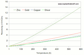
copper, silver, gold are not
superconductors even at absolute zero temperature, 0 K although their
resistance R decreases with temperature)
o.
Once current flows in superconductors, it needs no
further applied voltage (electric energy per coulomb) to persist flowing –
there is no loss of current.
p.
Superconductors
can produce magnets with magnetic field strengths > 10 times that of the
best normal electromagnets. These superconducting magnets are useful:
iii.
to produce computer
chips which are faster and smaller.
q.
Superconducting
wires or cables increase the
efficiency of electrical power transmission as loss of energy as heat is
greatly reduced.
r.
Students must be able to recognize the R
(Resistance) – T (Temperature) graphs of normal conductors (pl see below for copper), NTC thermistor (pl see below), RTD (below) and those of
superconductors (pg. 365).
------------------------------------------------------------------------------

-------------------------------------------------------------------------------
------------------------------------------------------------------------------

-------------------------------------------------------------------------------
----------------------------------------------------------------------------------------------
By: tutortan1@gmail.com (edited on 24/05/16)
No comments:
Post a Comment