Translate

Wednesday, 4 April 2012

Electromotive Force and Internal Resistance


1.      Electromotive force V(e.m.f.) of an electrical source is defined as the work done (W) by the source in driving per unit charge around a complete circuit: V(e.m.f.) = W/Q = E/Q.
      a.   A complete circuit consists of both the internal (within the source) and the external circuits (outside the source):
b.       An electrical source can be a cell, a battery or any other source of electricity.
c.      A cell uses chemical reaction to produce current – it converts chemical energy to electrical energy. A cell produces one directional current known as the DC current.
d.       A battery is a combination of 2 or more cells in series.

2.      Since it is energy that enables work to be done, electromotive force V(e.m.f.) can be alternatively viewed as the electrical energy E supplied or used by the source to drive per unit charge around a complete circuit:
                        V(e.m.f.) = W/Q = E/Q
                        V(e.m.f.) = W/It (since, Q = It as I = Q/t)
                        V(e.m.f) = P/I (since power P = W/t)
Therefore, electromotive force may also be defined as the ratio of the total power supplied to the whole circuit to the current flowing through it.

3.      Electromotive force V(e.m.f.) may be measured by:
               i.      A high-resistance voltmeter: By measuring the potential difference of the cell or electrical source in an open circuit – this is however not the true value because a small current still flows through the voltmeter and part of the electromotive force becomes part of the potential difference across the voltmeter itself;
             ii.      A cathode ray oscilloscope; or
            iii.      A potentiometer.

4.      Experimental evidence (pg. 379) shows that:
               i.      Electromotive force V(e.m.f.) is (approximately) the potential difference across the cell or source of electricity in an open circuit – when no current flows through the external circuit or through any external components (Yr 2005 SPM P1 Q38 at pg. 11).

             ii.      Electromotive force V(e.m.f.) is not the same as terminal potential difference Vt – i.e. it is not equal to the potential difference across a closed external circuit through which current is flowing:
V(e.m.f.) > terminal potential difference Vt:
V(e.m.f) > Vt or Vt < V(e.m.f) …(Yr 2011 SPM P1 Q36 at pg. 288)

5.      Lost volt or voltage drop (Vd) refers to: The difference between electromotive force E (or, V(e.m.f.) when circuit is open and terminal potential difference Vt (when circuit is closed) (Vd = V(e.m.f.) – Vt). Lost volt (Vd) is due to the internal resistance r of the cell or electrical source:
V(emf) – Vt = + Vd; or
V(emf) = Vt + Vd; or
Vt = - Vd + V(emf); or
Vt = -rI + V(emf)...(This linear equation is analogous to y = mx + c, y  = Vt; x = I; -r is the gradient m and V(e.m.f.) is the y-intercept of the linear graph)

6.      The internal resistance r of a cell is the resistance within the cell or within the internal circuit – that is, the resistance against the moving charge due to the electrolyte.
                                                                                                                    
7.      To show the existence of internal resistance: A torch is switched on for, say, 20 minutes and the dry cell in the torch becomes hotdue to internal resistance of the cell.

8.      Internal resistance r can be found:
               i.      By finding the voltage drop Vd over the current I flowing when the circuit closed; or
(Yr 2007 SPM P1 Q37 at pg. 100) / (Yr 2010 SPM P1 Q41 at pg. 241); or
             ii.      By finding the gradient of the Vt-I graph,
     where Vt = -rI + V(emf)
    (as in y = mx + c,
    Where, V(emf) is the y-intercept; and
     gradient m = internal resistance -r;
     see the experiment to determine V(emf) and r using the  formula, Vt = -rI + V(emf) at pg. 381)

--------------------------------------------
Updated By: tutortan1@gmail.com (8/4/12)

Series and Parallel Circuits

1.      What is an electrical circuit?
a.      An electric circuit is the path or network of paths formed by electrical components through which electric current flows when the circuit is closed.

b.      Electrical components that form a circuit with an electric source include:
                          i.      Resistor
                        ii.      Lamp
                      iii.      Switch
                      iv.      Electrical appliances
                        v.      Connecting wires

c.       Internal and external circuits:
                          i.      Internal circuit refers to the path taken by the current within the source (cell, battery, etc.).
                        ii.      External circuit refers the path taken by the current outside the source.

d.      Series and parallel circuits are 2 basic ways of connecting electrical components to form circuits for the current to flow.


2.      A series circuit refers to the single path formed by electrical components which are connected end to end consecutively to an electric source.

3.      In a series circuit, experimental evidence (at pg. 368) shows that:

a.       Potential difference (PD a.k.a. V):
                                       i.      PD applied across the external circuit = the SUM of individual PDs across each external component: V = V1 + V2 + V3 +…;
                                     ii.      In other words, the external components share the applied voltage across the external circuit;

                                    iii.      The electromotive force V(e.m.f.) or E of the cell (or battery) = the Sum of individual PDs across all components (including across the cell): V(e.m.f.) = V(drop) + V1 + V2 + …
                                   iv.      In other words, all the components in the circuit (incl. the cell) share the V(e.m.f.) of the cell.

b.      Current (I)
      SAME current flows through all the components: I = I1 = I2 = I3 =…;
(Yr 2006 SPM P1 Q42 at pg. 58)
(Yr 2009 SPM P1 Q38 at pg. 194)
(Yr 2010 SPM P1 Q39 at pg. 240)

c.       Resistance (R):
                                       i.      Effective Resistance = the SUM of individual resistance of each component: R = R1 + R2 + R3 ... (Also confirmed by: IR = IR1 + IR2 + IR3 + …).
                                     ii.      In other words:
1.      the effective resistance R in a series circuit is larger than each of the individual resistor;
2.      the combination of resistors in series effectively forms a longer resistor with higher resistance
                  (Yr 2006 SPM P1 Q39 at pg. 57)

4.      A parallel circuit refers to the network of separate and parallel paths formed by electrical components which are connected side by side and their corresponding ends are joined together to an electric source, a cell or a battery.

5.      In a parallel circuit, experimental evidence (at pg. 368) shows that:
    1. Potential difference (PD a.k.a. V):
                                                               i.      SAME PD (potential difference) across separate pathways: V = V1 = V2 = …;
                                                             ii.      In other words, voltage across each resistor in parallel is the same.
   (Yr 2005 SPM P1 Q43 at pg. 13)
(Yr 2007 SPM P1 Q36 at pg. 99)

    1. Current (I):
                                                               i.      The SUM of currents in separate pathways = Total current leaving or returning to cell: I = I1 + I2 + I3 + …;
                                                             ii.      In other words, resistors in parallel share the main current.
                                                            iii.      As current in each pathway is given by V/R, and V is the same for all pathways, therefore, main current = sum of individual currents also means:
               V/R = V/R1 + V/R2 + V/R3 + … (This leads us to the equation for effective resistance in a parallel circuit: 1/R = 1/R1 + 1/R2 + 1/R3 + …)

    1. Resistance (R):
                                                               i.      Effective resistance of resistors in parallel is given by: The reciprocal of the effective resistance = sum of the reciprocals of individual resistance in each pathway:
               1/R = 1/R1 + 1/R2 + 1/R3 + …
               (From: V/R = V/R1 + V/R2 + V/R3 + …, please see 5b(iii).)
            (Yr 2008 SPM P1 Q36 at pg. 147)

                                                             ii.      In other words:
1.      the effective resistance R in a parallel circuit is smaller than each of individual resistor;
2.      the combination of resistors in parallel effectively forms a resistor with larger cross-sectional area and therefore lower combined resistance.

                                                            iii.      When identical resistors are in parallel:
1.      Quick Formula to Calculate Effective Resistance:
      R(effective) = R(individual)/n
      Where, n = number of identical resistors in parallel

(Yr 2006 SPM P1 Q38 at pg. 57)
(Yr 2008 SPM P1 Q37 at pg. 148)
(Yr 2011 SPM P2 Q6 at pg. 301~302)

  1. Combined circuit refers to a circuit with series and parallel arrangements of components.
(Yr 2010 SPM P1 Q40 at pg. 241)
(Yr 2010 SPM P2 CQ12(b) at pg. 264~266)

Summary:

Ohm's law states that the current flowing, I through an ohmic conductor (pure metal) is directly proportional the potential difference, V across the conductor if the temperature remains constant.


----------------------------------------------------------------------------------


Example how to determine effective resistance of a parallel circuit:

  • When resistors are connected in parallel, the effective resistance becomes smaller compare to that of connection in series.
  • Thus, if terminal voltage Vt is the same, a higher main current will be shared by the individual resistors in parallel - thus each resistor will receive higher flow of current thereby producing a brighter bulb in parallel circuit

--------------------------------------------
Updated by: tutortan1@gmail.com (25/05/16)

Tuesday, 3 April 2012

7 Interesting SPM Paper 1 Questions on Waves (Yrs 2005 ~ 2011)


  1. Yr 2011, P1, Q32 (pg. 287): Which statement is correct when water waves are reflected by a reflector?
A.     The velocity of water waves before and after reflection are the same
B.     The wavelength of water waves become longer after reflection
C.     The amplitude of water waves becomes smaller after reflection

Comments: The publisher gives A as the answer which is not right because on reflection, the direction of waves changes – that means the velocity before and after the reflection CANNOT be the same. The effects of reflection are that the speed, frequency and the wavelength remain the same – thus B cannot be the answer also. You should choose C as the answer because on hitting the reflector, not all the wave energy is reflected - some will be transformed into heat and sound; and damping occurs as the reflected waves move along – all these means the reflected waves carry less energy and the amplitude becomes progressively smaller over time.

  1. Yr 2010, P1, Q25 (pg. 237): Which device is used to show that light is a transverse wave?
A. Glass Prism                          B. Double Slit              
C. Diffraction Grating                D. Polaroid block

Comments: You cannot find the answer from your F4 or F5 textbooks. Neither can you do so from the normal reference books. To get perfect scores in physics, you need to “google” for additional knowledge sometimes! The answer: D.

3        Yr 2008, P1 Q 33 (pg. 147): Which is the correct relationship between the wavelength of an electromagnetic radiation and the energy it carries?         
                  Wave length                 Energy carried
      A.        Short                            High
      B.        Short                           Low
      C.        Long                            High
      D.        Long                            Low

Comments: Again, this question is beyond Malaysian F4 & F5 physics textbooks and the normal physics reference books. But diligent students might already have known that the energy carried by photons of the electromagnetic radiation is given by the formula:
            E = h f
            Where, E = Energy,
                         h = Planck constant
                         f = frequency
Since, frequency f = Speed / wavelength and is therefore inversely proportional to wavelength with speed as a constant (3 x 10^8 m/s in vacuum or air approximately), short wavelength means high frequency means high energy (Answer: A); but, long wavelength also means short frequency and therefore low energy (Answer: D also). Answer: Both A and D.

4        Yr 2008, P1 Q34 (pg. 147): Diagram 19 shows the shape of a radio wave that is received by a simple radio receiver. What is the shape of the wave produced after it is passed through a diode?
      A, B, C or D.             Answer: A

Comments: Students who have studied the chapter on “Electronics” (F5 Chapter 4) should know that the answer is A. For those who have not studied “rectification” in electronics and do not know what a diode is, be patient, you will cover the chapter in due course.
                 
5        Yr 2006, P1 Q30 (pg. 55): The process of combining audio and radio frequency signals is known as:
A.     resonance
B.     damping
C.     modulation
D.     rectification

Comments: Surprisingly, "modulation" is not much talked about or discussed in any pages of Science Stream students' F5 Physics textbook BUT it talked about in greater details in pg. 189 of Arts Stream students' F5 Science textbook…A case of examiners got mixed-up?..hehehe :) Anyway, if this year, examiners ask: What is the device that combines a modulator and a demodulator (or, a demodulator and a modulator)? The answer is: “modem”. The amplitude modulated (AM) wave form is tested in next question.  
The answer to this Q30: C. modulation

6. Yr 2005, P1 Q29 (pg. 9): Which graph represents amplitude modulated waves?
A, B, C or D.                    Answer: A

Comments: Again, amplitude modulated wave form is not shown in any pages of F5 Physics textbook of Science Stream students BUT in pg. 189 of F5 Arts Stream students’ Science textbook. What if in Yr 2012, the examiners rephrase this Q29 to ask about frequency modulated (FM) wave form instead? The answer should then be: C (where you notice the period T for each successive wave cycle progressively increases and then decreases and the modulation of the frequency continues). Click here to see the AM and FM wave forms in greater clarity.

  1. Yr 2005, P1 Q35 (pg. 11): The graphs show the cross-sections of the water waves. Which wave has the greatest energy?
A, B, C or D.               Answer: C (for water waves)

Comments: Wave C has the highest amplitude (and thus the wave height). Wave D has the highest frequency. For water waves, energy is proportional to the square of its wave height – thus C is the answer for water waves. But if it were electromagnetic waves, the answer would be D because energy of photons of electromagnetic waves is proportional to frequency of the electromagnetic waves (E = h f, where E is energy; h is Planck’s constant and f is frequency of the waves).

Summary - SPM Past Year Questions on Electricity


Summary - SPM Past Year Questions - “Electricity” (Form 5 Chapter 2):

Year
Paper 1 (50 Qs)
(1hr 15min)
Paper 2
(2hr 30min)
A: 8 Qs – Do All
(90 min, 60 pts)
B: 2 Qs – Do 1Q
(30 min, 20 pts)
C: 2 Qs – Do 1Q
(30 min, 20 pts)
Paper 3
(1hr 30min)
A: 2 Qs (28 pts)
(advice: 1 hr)
B: 2 Qs – Do 1Q
(30 min, 12 pts)
2011
Q35~39 (5Qs)
Pgs 288~289
A.   Q6
Pg 301
NIL
2010
Q33/38~41(5Qs)
Pgs 239~242
C.Q12
Pgs 264-265

NIL
2009
Q35~38 (4Qs)
Pgs 194
C.Q12
Pg 216
NIL
2008
Q35~38 (4Qs)
Pgs 147~148
A.Q3
Pgs 156 ~157
NIL
2007
Q35~38 (4Qs)
Pgs 99~100
A.Q6
Pgs 111~112
A.Q1 (Pg 128)
2006
Q36/38~40
Q42 (5Qs)
Pgs 57~58
A.Q1
Pg 62

A.Q2 (Pg 85)
2005
Q38/39
Q42/45 (6Qs)
Pgs 11~13
NIL
A.Q2 (Pg 41)
Comments:
Try Yr 2010 Paper 2 Section C Q12 - Should be interesting. If it's a breeze, you should do well on "Electricity". If you don't know, take physics tuition from me; or email: tutortan1@gmail.com;


Sunday, 1 April 2012

Potential Difference, Current and Resistance

1.      Just as an object placed at different depths of water experiences different water pressures, or, an object at different distances from the centre of the earth carries different gravitational potential energies, a charged particle placed at different points of an electric field also experiences different electric forces acting on it and carries different electric potential energies.

2.      The potential difference or voltage between 2 points in an electric field is defined as the work done in moving 1 coulomb of charge from 1 point to the other. Suppose, work, W is done to move a charge, Q from 1 point to another, the potential difference, V is given by:
Potential difference = Work done / Charge;
V = W / Q

3.      The potential difference (a.k.a. voltage) between  2 points is 1 volt if 1 joule of work is required to move a charge of 1 coulomb from 1 point to the other:
1 volt = 1 joule / 1 coulomb = 1 J C-1 = 1 V (unit symbol for volt)

4.      Just as it is the pressure difference that causes water to move from a region of higher pressure to a region of lower pressure, or an object to move from high ground to low ground due to different gravitational potential energies, a charged particle too would move from a point of higher electric potential (+ve) to another point of lower electric potential (-ve) in an electric field or circuit – due to the potential difference between the 2 points.

5.      The movement of charged particles from 1 point to another in an electric field or a circuit due to the potential difference between the 2 points produces an electric current. The direction of flow of current is by convention also from positive to negative. The rate of flow of the charge determines the size of the current. But what determines the rate of flow of the charge? Read on…

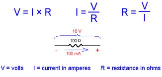
6.      Ohm’s law (by a German physics teacher, Georg Simon Ohm in 1826) states that the current flowing through an ohmic conductor is directly proportional to the potential difference across its ends provided that its temperature and other physical conditions (length, cross-sectional area and material type) remain constant:
I = Constant x V; or,
V = Another constant x I (This other constant is known as the resistance, R)
V = R x I = IR (R is the gradient of a linear V-I graph for ohmic conductor); or
R = V/I (R is the ratio of instantaneous voltage over current for all conductors); or
I = V/R (I is also the ratio of voltage over resistance)
(Yr 2010 SPM P1 Q38 at pg. 240)

7.      Thus, the V-I graphs:
a.       of all ohmic conductors are linear graphs which pass through the origin and their gradients are the resistances R of the respective ohmic conductors – the steeper the gradient, the higher the resistance;
                    

b.      of non-ohmic conductors are non-linear which pass through the origin and the ratio of V over I at any point of the V-I graph gives the value of resistance at that point – the higher the ratio, the higher the resistance.
(Yr 2006 SPM P1 Q36 at pg. 57)

8.      Resistance, R of a conductor is therefore defined as the ratio of the potential difference V across the conductor to the current I flowing through it. This applies to both ohmic and non-ohmic conductors. The unit of measurement of resistance R is therefore volt per ampere (V A-1) or ohm (Ω).

9.      Factors that affect the resistance R of a conductor are (experiments at pgs 357 ~ 362):
c.       Its length, l – (directly proportional) the longer the length, the higher the resistance;
d.      Cross-sectional area, A – (inversely proportional) the bigger the area, the lower the resistance;
e.       The type of material – resistivity ρ depends on material; and,
f.        Its temperature :
·        Most Pure metal - (proportional): the higher the temperature, the higher the resistance.
·        Alloys (constantan, nichrome) – resistance increases slightly with temperature increases.
·        Thermistor resistance decreases greatly with slight increase in temperature.
·        Superconductor – resistance becomes zero at critical low temperature.

(Yr 2007 SPM P1 Q35 at pg. 99)
(Yr 2009 SPM P1 Q37 at pg. 194)
------------------------------------------------------------------------------------------

More on Thermistor (Negative Temperature Coefficient, Thermistor)

Thermistors work by translating temperature into resistance, with resistance decreasing as temperature increases (referred to as a 'negative temperature coefficient’, or NTC, thermistors).

The graph below illustrates the resistance of the thermistor as a function of the temperature:

Thermistor Resistance vs. Temperature Graph
A graph of the resistance vs temperature of a typical 10K thermistor

As can be seen from the graph, the resistance of the thermistor drops very quickly in the temperature range 0°C to 40°C - it offers good sensitivity to changes in temperature in this range; however, at much higher temperatures, it will be less sensitive to temperature changes.

10.  The resistance R of a resistor of a given material and at a given temperature can be calculated using this relationship: R = ρ l/A, where R is directly proportional to length l and resistivity ρ of the resistor and is inversely proportional to cross-sectional area A of the same. Resistivity ρ of a resistor at a given temperature is a constant dependent on the material of the resistor. Thus,
                        R = ρ l/A; or,
                        ρ = RA/l

11.  Voltmeter:
g.       It measures potential difference or voltage in volts (V);
h.       It is connected in parallel across the resistor or device;
i.         It has high resistance so that the current flowing through it is negligible.

12.  Ammeter (or milliammeter):
j.        It measures current in amperes (A) (or milliamperes, mA);
k.      It is connected in series with the resistor or component;
l.         It has low resistance so that its existence has insignificant effect on the magnitude of current flowing and to be measured.

13.  Measurement of Resistance: To measure resistance, we usually take the reading of the voltmeter in volts across the resistor over the reading of the ammeter for the current flowing through the resistor. Thus, R = V/I    (Instead of using the formula: R = ρ l/A, which we can use too if resistivity ρ, length l and cross sectional area A are all readily and accurately measurable or available) 

14.  Superconductors:
m.   What are superconductors? Superconductors are materials which offer no resistance (i.e. zero resistance) to the flow of current when they are cooled to below certain temperatures known as the critical temperatures for superconductivity.

n.       Only some metals show superconductivity, for examples:
Name of Elements              Critical Temperature (K)
Zinc, Zn                                          0.88
Aluminium, Al                                 1.14
Tin, Sn                                           3.69
Mercury, Hg                                   4.15
Lead, Pb                                        7.26
Niobium, Nb                                  9.2

(Some of the best conductors of electricity at normal temperature like copper, silver, gold are not superconductors even at absolute zero temperature, 0 K although their resistance R decreases with temperature)

o.      Once current flows in superconductors, it needs no further applied voltage (electric energy per coulomb) to persist flowing – there is no loss of current.

p.      Superconductors can produce magnets with magnetic field strengths > 10 times that of the best normal electromagnets. These superconducting magnets are useful:
                                                   i.      in the development of magnetically levitated trains and vehicles of the future;
                                                 ii.      in Magnetic Resonance Imaging (MRI) scanner as diagnostic tool in medicine
                                                iii.      to produce computer chips which are faster and smaller.

q.      Superconducting wires or cables increase the efficiency of electrical power transmission as loss of energy as heat is greatly reduced.

r.        Students must be able to recognize the R (Resistance) – T (Temperature) graphs of normal conductors (pl see below for copper), NTC thermistor (pl see below), RTD (below) and those of superconductors (pg. 365).

                  Image result for resistance v temperature of normal resistors
------------------------------------------------------------------------------
 Thermistor Graph
-------------------------------------------------------------------------------


          ----------------------------------------------------------------------------------------------


By: tutortan1@gmail.com (edited on 24/05/16)

Electric Charge and Electric Field

Electric Charge

1.      What is an electric charge? An electric charge is anything that produces an electric field in the space around it. It can be positive or negative.

2.      An electric charge can be: an electron, a proton, a nucleus (an alpha particle i.e. helium nucleus), an ion, a charged molecule or any charged object such as a charged cloud, a plastic comb, an electrode or the charged dome of the Van de Graaff generator:
       * Like charges repel
       * Unlike charges attract

3.      When there is a flow of electric charge, there is an electric current – this is shown by the “Van de Graaff Generator and Galvanometer” experiment (pg. 43 of F5 textbook).

4.      Electric charge Q is a derived quantity and its unit of measurement coulomb C is a derived unit:
 
    1. The amount of electric charge Q flowing through a point in a circuit is given by the product of current, I, and time of flow of the current, t, across the point, that is:
                  Q = I x t …………….(Yr 2005 SPM P1 Q42 at pg. 12);
                                                      (Yr 2007 SPM P1 Q38 at pg. 100)

Alternatively, Q = ne
(where n = number of electrons or protons; e = charge of an electron or proton)

    1. Accordingly (from Q = I x t), electric current is the rate of charge flow of electric charge:
I = Q / t…………….. (Yr 2011 SPM P1 Q35 at pg. 288)

    1. Notwithstanding the foregoing, students must know that electric current is a base quantity (i.e. a fundamental physical quantity). And, SI (International System of Units) defined the base unit for electric current ampere, A in terms of its electromagnetic force effect (rather than rate of flow of electric charge), as follows:
One ampere is the constant current which - if maintained in 2 straight parallel conductors of infinite length, of negligible cross-sectional area, and placed 1 metre apart in a vacuum - produces a force of 2 x 10-7 newton per metre of length.”

5.      An electron carries an electric charge e = - 1.6 x 10-19 C. If a steady current of 1 A is flowing for 1 second past a point in a circuit:
    1. the electric charge flowing past is Q = I x t = 1 A x 1 s = 1 C. And,
    2. therefore, the number of electrons flowing past the point to give 1 C of electric charge = 1 / 1.6(10-19) = 6.25 x 1018 electrons.

Electric Field

1.   What is an electric field? An electric field is the space around a positive or negative electric charge in which any other electric charge would experience an electrical force acting on it.  
      (Yr 2005 SPM P1 Q45 at pg. 13)

2.      An electric field can be represented by arrowed lines known as the electric field lines or the electric lines of force.

3.      By convention, the direction of electric field lines is from positive to negative – that is, the path that would be taken by a positive test charge if placed in the electric field.
                                          
4.      The closer the electric field lines, the stronger the electric force.

5.      An electric field line is a vector quantity because it has magnitude and direction of force.

6.      The pattern of electric field lines depends on the shape and the number of the charged objects in the vicinity (Refer: “Semolina Powder on Olive Oil and Metal Electrodes” experiment for the various patterns – pg.349) (Yr 2008 SPM P1 Q35 at pg. 147)

      The Electric Field Pattern:


7.      The effect of electric field on a charge can be illustrated by
                                                         i.      Polystyrene (Ping-Pong) Ball” Experiment (Click the link to see video showing this) (or, see pg. 350 of Fajar Oxford Reference Book); and,
(Yr 2010 SPM P1 Q33 at pg. 239)
                                                       ii.      “Candle Flame” Experiment (pg.351 or pg 46 of F5 textbook).
(Yr 2011 SPM P1 Q37 at pg. 288)
(Yr 2010 SPM P2 CQ12(a) at pg. 264)


Candle Flame in the electric field
  • Heat energy from the candle flame produces ionization of air molecules to form positive and negative ions.
  • Movement of positive ions which are heavier towards the negative plate causes a bigger spread of the flame.
  • Negative electrons which are lighter move towards the positive plate and causing a smaller spread of the flame. (E.H.T. voltage supply means "extra high tension" voltage supply)


-------------------------------------------
Updated by: tutortan1@gmail.com(23/06/16)