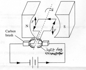
- Interaction of Magnetic Fields:
The Resultant Field with Catapult Effect (a.k.a. Catapult Field)
i.
Just as two bar magnets coming within the
magnetic field of each other would experience a force – a push (repulsion) or a
pull (attraction) depending on the positions of their magnetic poles:
i.
a current-carrying
conductor (which has magnetic field around it) would similarly experience a magnetic force when its
magnetic field interacts with the magnetic field of another magnet.
ii.
The interaction produces a resultant magnetic field (a.k.a. catapult field) with magnetic
field lines wrapping around the conductor like the stretched catapult producing a catapult effect – that moves
the conductor from stronger region of the magnetic field to weaker region.
iii.
Drawing the ‘catapult field’ is one way to
determine the direction of movement of the current-carrying conductor in a
magnetic field – however, it could be time-consuming. A much simpler method is
by the use of Fleming’s Left-hand Rule
(or Motor Rule):

Alternatively, the Right-hand Slap Rule where the four fingers of the right point in the direction of the magnetic field B and the thumb points in the direction of the current I, the direction of slapping would be the direction of force F on the conductor.:

iv.
Interestingly, the magnetic field of a
current-carrying conductor itself would also exert a force on the other magnet
which field exerts a force on it - as Hans Christian Oersted discovered in
1820 when the pointer of a compass moved when current was switched on in a
nearby circuit – It is this discovery which led to the theory of electromagnetism
and its many useful applications.
ii.
Fleming’s
Left Hand Rule (Motor Rule)
Please see above for the diagram.
iii.
Factors
Affecting Magnitude of the Force on Current-Carrying Conductor in a Magnetic
Field:
i.
Magnetic Field Strength (of the other magnet)
ii.
Size of Current (in the conductor causing
induced magnetic field)
iii.
Length of Wire or Conductor in the Field
iv.
Angle between Magnetic Field (B) and the Current
(I)
iv.
Force
between Two Current-Carrying Conductors:

i.
The magnetic fields of two current-carrying
conductors would interact with each other as would the fields of two
permanent magnets.
ii.
If the two conductors are near (but not next) to
each other:
i.
They attract each other when the current is
flowing in the same direction in both of them;
ii.
They repel each other when the current is
flowing in the opposite direction.
The direction of movement of the
conductor can be determined by any of the following methods:
a.
Plotting the catapult field
b.
Fleming’s Left-hand Rule
c.
Right-hand Slap Rule
iii.
If the two conductors are next to each other:
i.
They interact to produce a stronger magnetic
field when the current is flowing in the same direction in both of them;
ii.
They interact to produce a weaker or neutral
field when the current is flowing in the opposite direction.
v.
Turning
Effect of a Current-Carrying Coil in a Magnetic Field


i.
For a coil placed in a magnetic field, when the
current flows through it, it flows in opposite directions in opposing arms of
the coil – concentric magnetic field lines in opposite directions are therefore
produced around both arms.
ii.
These induced magnetic fields interact with the
external magnetic field. The resultant magnetic field produces a catapult
effect in opposite directions for opposing arms of the coil – forming a couple
which produces a turning effect and so the coil rotates.
iii.
The direction of rotation of the coil would reverses
when:
i.
The current reverses
ii.
The external magnet poles reverse
The direction of rotation of the
coil can be determined by:
1.
Plotting the catapult field; or,
2.
Fleming’s Left-hand Rule; or,
3.
Right-hand Slap Rule
vi.
D.C.
Motor – Factors Affecting Speed of Rotation

i. The diagram above shows the construction features of a simple dc motor.
ii.
A dc motor consists of a rectangular coil of
wire placed between two permanent magnets (a.k.a. the external magnets).
iii.
Both ends of the coil are soldered to a commutator
made up of two semi circular copper rings.
iv.
Two carbon brushes are held against the
commutator with slight pressure with the help of springs.
v.
Because of the commutator, current always flow
in the same direction for the arm near to the north-pole of the external magnet
and in the opposite direction for the other arm of the coil. As a result, the
coil rotates in one direction.
vi.
The speed of rotation of the coil can be
increased if any of these is increased:
1.
The Magnetic Field Strength (of the external
magnet)
2.
The Current flowing in the coil (causing stronger
induced magnetic field)
3.
The Number of Turns in the Coil (causing stronger
induced magnetic field)
4.
The Area of the Coil
------------------------------------------------------------

No comments:
Post a Comment